Datei:US392729 Henchoz.jpg: Unterschied zwischen den Versionen
Holger (Diskussion | Beiträge) Keine Bearbeitungszusammenfassung |
Holger (Diskussion | Beiträge) Keine Bearbeitungszusammenfassung |
||
| (11 dazwischenliegende Versionen desselben Benutzers werden nicht angezeigt) | |||
| Zeile 1: | Zeile 1: | ||
'''[[Datei Diskussion:US392729 Henchoz.jpg|<<< bearbeitete Google-Übersetzung des Patenttextes]] | |||
''' | |||
== Patenttext: == | |||
To all whom it may concern:<br> | To all whom it may concern:<br> | ||
Be it known that we, Auguste Henchoz and Fritz Henchoz, both residing at Locle, in Switzerland, have invented a new and useful Improvement in Stop-Watches, of which the following is a speeification.<br> | Be it known that we, Auguste Henchoz and Fritz Henchoz, both residing at Locle, in Switzerland, have invented a new and useful Improvement in Stop-Watches, of which the following is a speeification.<br> | ||
| Zeile 5: | Zeile 10: | ||
Figure 1 is a top view of the general arrangement of the stop mechanism; and Fig. 2 shows, on an exaggerated scale, the section of the pinion of the first wheel (center wheel) of the works, with the axis of the stop-hand traversing the same.<br> | Figure 1 is a top view of the general arrangement of the stop mechanism; and Fig. 2 shows, on an exaggerated scale, the section of the pinion of the first wheel (center wheel) of the works, with the axis of the stop-hand traversing the same.<br> | ||
The push-piece which acts upon the camratchet '''G''' and the corresponding spring are not shown in the drawings, being of the usual construction. Upon the axis '''A''' of the secondswheel there is fixed a fine toothed wheel '''B''', which turns continuously with the axis '''A'''. The arbor of the pinion '''C''' and center or first wheel is hollow, and within it is the axis '''D''', the pivot '''d''' of wich passes through a little tube or plug '''c''', inserted into the tubular arbor '''C''', and this axis '''D''' carries the hand '''E''' of the stop mechanism. The axis '''D''' also carries a fine-toothed pinion '''H''' and an eccentric or heart-cam '''I''', the latter being acted upon by a lever '''J''',when the hand '''E''' is to be returned to its normal position of rest. This lever '''J''' is acted upon, as usual, by the cam-ratchet '''G'''. The other end of the axis '''D''' to the hand is provided with a pivot '''d'''', turning in the oscillating bridge '''F'''. This latter oscillates about a screw '''f''' and has a projection '''F'''', which bears alternately upon a cam or in a notch of the cam-ratchet '''G'''. According to the position assumed by the bridge '''F''' the pinion '''H''' is brought into or thrown out of gear with the wheel '''B''' - that is to say, that the stop-hand '''E''' is put into action or stopped by slightly moving the oscillating bridge '''F'''.<br> | The push-piece which acts upon the camratchet '''G''' and the corresponding spring are not shown in the drawings, being of the usual construction. Upon the axis '''A''' of the secondswheel there is fixed a fine toothed wheel '''B''', which turns continuously with the axis '''A'''. The arbor of the pinion '''C''' and center or first wheel is hollow, and within it is the axis '''D''', the pivot '''d''' of wich passes through a little tube or plug '''c''', inserted into the tubular arbor '''C''', and this axis '''D''' carries the hand '''E''' of the stop mechanism. The axis '''D''' also carries a fine-toothed pinion '''H''' and an eccentric or heart-cam '''I''', the latter being acted upon by a lever '''J''',when the hand '''E''' is to be returned to its normal position of rest. This lever '''J''' is acted upon, as usual, by the cam-ratchet '''G'''. The other end of the axis '''D''' to the hand is provided with a pivot '''d'''', turning in the oscillating bridge '''F'''. This latter oscillates about a screw '''f''' and has a projection '''F'''', which bears alternately upon a cam or in a notch of the cam-ratchet '''G'''. According to the position assumed by the bridge '''F''' the pinion '''H''' is brought into or thrown out of gear with the wheel '''B''' - that is to say, that the stop-hand '''E''' is put into action or stopped by slightly moving the oscillating bridge '''F'''.<br> | ||
A spring '''M''', presses the bridge '''F''' in the direction of the wheel '''B''', and thereby causes the pinion '''H''' to be put into gear with the wheel '''B''' as soon as the projection F' falls into one of the notches of the cam '''G'''.<br> | |||
A friction-spring '''K''', bears continually against the axis '''D''' and acts like a brake when the pinion '''H''' is out of gear. Fig. 2 shows the axis '''D''' in position for the hand to be rotated.<br> | |||
We are aware that in stop-watches the axis '''D''' of the stop-hand has passed through the tubular arbor of the center- or first-wheel and has been fitted so as to oscillate within said arbor, and we are aware that rotation has been given to the arbor of the stop-hand by a wheel upon the arbor of the third wheel acting through an intermediate wheel or pinion. In our improvement the intermediate gear wheel is dispensed with, and the axis '''D''' is supported by and moves with the bridge '''F''', and said bridge becomes a lever that swings upon the pivot '''f''', and it is not necessary tco slot or elongate the hole for the pivot of the axis '''D''', as has heretofore been usual when thEe axis was moved laterally to connect or disconnect the gear-wheels driving the independent seconds-hand.<br> | |||
We claim as our invention:<br> | |||
1. The combination,with the center pinion '''C''', having a tubular arbor, of the wheel '''B''' upor the arbor of the seconds-wheel of the watchmovement, the axis '''D''', passing through the tubular arbor, the hand '''E''', pinion '''H''', and heart-cam '''I''' upon the axis '''D''', and the leverbridge '''F''', pivoted at '''f''' and having a hole for the pivot of the axis '''D''', and the cam ratchet-wheel '''G''', for giving motion to the lever-bridge and moving the axis and pinion laterally for stopping and starting the seconds-hand, substantially as specified.<br> | |||
2. In a stop-watch, the combination, with the wheel '''B''' and cam ratchet-wheel '''G''', of the lever-bridge '''F''', the axis '''D''', having its pivot in a hole in the lever-bridge, the heart-cam '''I''', pinion '''H''', and hand '''E''' upon the axis '''D''', and a spring acting to press the bridge and pinion '''H''' toward the wheel '''B''', substantially as set forth.<br> | |||
:Auguste Henchoz | |||
:Fritz Henchoz | |||
{{Kategorie Bildgalerie Archiv Henchoz Frères}} | {{Kategorie Bildgalerie Archiv Henchoz Frères}} | ||
Aktuelle Version vom 29. September 2012, 10:39 Uhr
<<< bearbeitete Google-Übersetzung des Patenttextes
Patenttext:
To all whom it may concern:
Be it known that we, Auguste Henchoz and Fritz Henchoz, both residing at Locle, in Switzerland, have invented a new and useful Improvement in Stop-Watches, of which the following is a speeification.
This Invention consists in a stop mechanism of a very cheap construction, in which the hand of the stop mechanism is directly acted upon by a wheel fixed to the axis of the seconds-wheel of the train without any intertmediate transmission.
The accompanying drawings show a stop mechanism constructed according to this invention.
Figure 1 is a top view of the general arrangement of the stop mechanism; and Fig. 2 shows, on an exaggerated scale, the section of the pinion of the first wheel (center wheel) of the works, with the axis of the stop-hand traversing the same.
The push-piece which acts upon the camratchet G and the corresponding spring are not shown in the drawings, being of the usual construction. Upon the axis A of the secondswheel there is fixed a fine toothed wheel B, which turns continuously with the axis A. The arbor of the pinion C and center or first wheel is hollow, and within it is the axis D, the pivot d of wich passes through a little tube or plug c, inserted into the tubular arbor C, and this axis D carries the hand E of the stop mechanism. The axis D also carries a fine-toothed pinion H and an eccentric or heart-cam I, the latter being acted upon by a lever J,when the hand E is to be returned to its normal position of rest. This lever J is acted upon, as usual, by the cam-ratchet G. The other end of the axis D to the hand is provided with a pivot d', turning in the oscillating bridge F. This latter oscillates about a screw f and has a projection F', which bears alternately upon a cam or in a notch of the cam-ratchet G. According to the position assumed by the bridge F the pinion H is brought into or thrown out of gear with the wheel B - that is to say, that the stop-hand E is put into action or stopped by slightly moving the oscillating bridge F.
A spring M, presses the bridge F in the direction of the wheel B, and thereby causes the pinion H to be put into gear with the wheel B as soon as the projection F' falls into one of the notches of the cam G.
A friction-spring K, bears continually against the axis D and acts like a brake when the pinion H is out of gear. Fig. 2 shows the axis D in position for the hand to be rotated.
We are aware that in stop-watches the axis D of the stop-hand has passed through the tubular arbor of the center- or first-wheel and has been fitted so as to oscillate within said arbor, and we are aware that rotation has been given to the arbor of the stop-hand by a wheel upon the arbor of the third wheel acting through an intermediate wheel or pinion. In our improvement the intermediate gear wheel is dispensed with, and the axis D is supported by and moves with the bridge F, and said bridge becomes a lever that swings upon the pivot f, and it is not necessary tco slot or elongate the hole for the pivot of the axis D, as has heretofore been usual when thEe axis was moved laterally to connect or disconnect the gear-wheels driving the independent seconds-hand.
We claim as our invention:
1. The combination,with the center pinion C, having a tubular arbor, of the wheel B upor the arbor of the seconds-wheel of the watchmovement, the axis D, passing through the tubular arbor, the hand E, pinion H, and heart-cam I upon the axis D, and the leverbridge F, pivoted at f and having a hole for the pivot of the axis D, and the cam ratchet-wheel G, for giving motion to the lever-bridge and moving the axis and pinion laterally for stopping and starting the seconds-hand, substantially as specified.
2. In a stop-watch, the combination, with the wheel B and cam ratchet-wheel G, of the lever-bridge F, the axis D, having its pivot in a hole in the lever-bridge, the heart-cam I, pinion H, and hand E upon the axis D, and a spring acting to press the bridge and pinion H toward the wheel B, substantially as set forth.
- Auguste Henchoz
- Fritz Henchoz
Dateiversionen
Klicke auf einen Zeitpunkt, um diese Version zu laden.
| Version vom | Vorschaubild | Maße | Benutzer | Kommentar | |
|---|---|---|---|---|---|
| aktuell | 13:02, 11. Aug. 2012 | 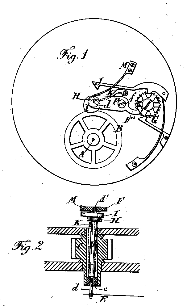 | 606 × 991 (225 KB) | Holger (Diskussion | Beiträge) | {{Kategorie Bildgalerie Archiv Henchoz Freres}} |
Du kannst diese Datei nicht überschreiben.
Dateiverwendung
Die folgende Seite verwendet diese Datei: