Datei:US392729 Henchoz.jpg

Originaldatei (606 × 991 Pixel, Dateigröße: 225 KB, MIME-Typ: image/jpeg)
To all whom it may concern:
Be it known that we, Auguste Henchoz and Fritz Henchoz, both residing at Locle, in Switzerland, have invented a new and useful Improvement in Stop-Watches, of which the following is a speeification.
This Invention consists in a stop mechanism of a very cheap construction, in which the hand of the stop mechanism is directly acted upon by a wheel fixed to the axis of the seconds-wheel of the train without any intertmediate transmission.
The accompanying drawings show a stop mechanism constructed according to this invention.
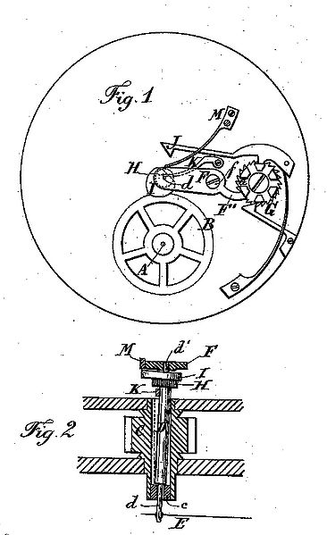
Figure 1 is a top view of the general arrangement of the stop mechanism; and Fig. 2 shows, on an exaggerated scale, the section of the pinion of the first wheel (center wheel) of the works, with the axis of the stop-hand traversing the same.
The push-piece which acts upon the camratchet G and the corresponding spring are not shown in the drawings, being of the usual construction. Upon the axis A of the secondswheel there is fixed a fine toothed wheel B, which turns continuously with the axis A. The arbor of the pinion C and center or first wheel is hollow, and within it is the axis D, the pivot d of wich passes through a little tube or plug c, inserted into the tubular arbor C, and this axis D carries the hand E of the stop mechanism. The axis D also carries a fine-toothed pinion H and an eccentric or heart-cam I, the latter being acted upon by a lever J,when the hand E is to be returned to its normal position of rest. This lever J is acted upon, as usual, by the cam-ratchet G. The other end of the axis D to the hand is provided with a pivot d', turning in the oscillating bridge F. This latter oscillates about a screw f and has a projection F', which bears alternately upon a cam or in a notch of the cam-ratchet G. According to the position assumed by the bridge F the pinion H is brought into or thrown out of gear with the wheel B - that is to say, that the stop-hand E is put into action or stopped by slightly moving the oscillating bridge F.
A. spring, M, presses the bridge F in the dipinion 11 to be put into gear with the whee B as soon as the projeetion F' falls. into one o the notches of the cam G.
-A frietion - spring, K, bears eontinuallj .against the axis D and acts like a brake whei tbe pinion H is out of gear. Fig. 2 shows th~ axis D in position for the hand to be rotated
We are aware that in stop-watches the axi: D of the stop-hand has passed through tb tubular arbor of the center or first wheel auf has been fitted so as to oscillate within saic arbor, and we are aware that rotation bw been given to the arbor of the stop-hand by
wheel upon the arbor of the third wheel act ing through an intermediate wheel or pinion, In our irnprovement the intermediate gear wheel is dispensed with, and the axis D i; supported by and moves wich the bridge E, and Said bridge becomes a lever that swing upon the pivot f, and it is not necessary tc slot or elongate the hole for the pivot of thE axis D, as has heretofore been usual whenn thE axis was tnoved laterally to conneet or diseonnect the gear-wheels driving the independent seconds-hand.
We claim as our invention-
1. The combination,with the center pinion, C, having a tubular arbor, of the wheel B upor the arbor of the seconds-wheel of the watchmovenient, the axis D, passing through thE tubular arbor, the hand ?., pinion II, and heart-cam I upon the axis D, and the leverbridge F, pivoted at f and having a hole foi the pivot of the axis D, and the cam ratchetwheel G, for giving motion to the lever-bridgE and moving the axis and pinion laterally foi stopping and starting the seconds-hand, substantially as specified.
2. In a stop-watch, the combination, with the wheel B and cam ratchet-wheel G, of the lever-bridge F, the axis D, having its pivot in a hole in the lever-bridge, the heart-cam 1, pinion H, and hand E clpon the axis D, and a spring acting to press the bridge and pinion H toward the wheel B, substantially as set forth.
AUGUSTE HENCHOZ. FRITZ H a °iN HOZ.
An alle, die es angeht:
Es wird bekannt gemacht, dass wir, Auguste Henchoz und Fritz Henchoz, beide wohnhaft in Locle, in der Schweiz, eine neue und nützliche Verbesserung an Stop-Uhren erfunden haben, deren Eigenschaften im Folgenden beschrieben ist.
Diese Erfindung besteht aus einem Stoppmechanismus in sehr preiswerter Ausführung, bei der der Zeiger des Stoppmechanismus direkt auf einem Rad sitzt, welches durch das, auf der Achse des Sekunden-Rades des Werkes angebrachte Sekundenübertragungsrad B, direkt (ohne Zwischenräder) angetrieben wird.
Die beigefügten Zeichnungen zeigen einen Stoppmechanismus, gemäß dieser Erfindung.
Bild 1 ist eine Draufsicht auf die allgemeine Anordnung des Stoppmechanismus, und Bild 2 zeigt in einem vergrößerten Maßstab den Schnitt durch das Trieb des Minutenrades mit dem zentralen Stoppsekundenrad, auf dem der Stoppsekundenzeiger sitzt.
Der Drücker, welcher auf das Schaltrad G wirkt und die Schaltradfeder sind in den Zeichnungen nicht dargestellt, da in der üblichen Bauweise ausgeführt. Auf der Achse A des Sekundenrades ist ein fein verzahntes Rad B angebracht, welches sich kontinuierlich mit dem Sekundenrad dreht. Die Welle C des Minutenrades ist hohl und in ihr dreht sich die Achse D, deren Zapfen d im Schwenkkloben F bzw. d' (auf diesem Zapfen sitzt der Stoppsekundenzeiger E) in der Buchse C gelagert sind. Die Achse D trägt auch ein feinverzahntes Ritzel H und einen exzentrischen Nocken oder Herz-I, wobei letztere beaufschlagten Hebel J, wenn die Hand E in seine normale Ruhestellung zurückgeführt werden soll. Dieser Hebel J beaufschlagt, wie üblich, durch den Nocken-Ratsche G. Das andere Ende der Achse D auf die Hand mit einem Gelenk d 'vorgesehen, Drehen in der Schwingbrücke F. Diese letztere oszilliert um eine Schraube f und einen Vorsprung F ', die abwechselnd auf einem Nocken trägt oder in einer Aussparung des Nocken-Ratsche G. Je nach Stellung durch die Brücke F das Ritzel H in gebracht wird oder aus der Getriebe mit dem Rad B geworfen angenommen - das heißt zu sagen, dass der Anschlag-Hand-E in Aktion gesetzt wird oder durch leichtes Verschieben der schwingenden Brücke F. gestoppt.
Eine Feder M drückt der Brücke F in Richtung des Rades B und bewirkt dadurch, dass das Ritzel, um in H Zahnrad mit dem Rad B, sobald der Vorsprung F 'fällt werden in eine der Kerben des Nockens gebracht G.
Eine Reibung Frühjahr K, trägt ständig gegen die Achse D und wirkt wie eine Bremse, wenn das Ritzel H außerhalb des Getriebes. Fig. 2 zeigt die Achse D in Position für die Hand gedreht werden.
Wir sind uns bewusst, dass in Stoppuhren die Achse D des Stop-Hand hat durch den röhrenförmigen Laube von der Mitte-oder First-Rad geleitet und wurde so zum Schwingen innerhalb der Laube ausgestattet, und wir sind uns bewusst, dass die Rotation wurde angesichts der Laube des Stop-Hand von einem Rad auf der Laube des dritten Rades handelnd durch ein Zwischenrad oder Ritzel. In unserem Verbesserung der Zwischenabschnitt Zahnrad verzichtet wird, und die Achse D durch und bewegt sich mit der Brücke F abgestützt ist und die Brücke wird, dass ein Hebel auf dem Drehzapfen schwingt f, und es nicht notwendig ist tco länglichen Schlitz oder das Loch für der Drehpunkt der Achse D, wie bisher üblich gewesen, wenn dir Achse wurde seitlich zu verbinden oder trennen Sie die Zahnräder den Antrieb des unabhängigen Sekundenzeiger bewegt.
Wir behaupten, als unsere Erfindung:
- 1. Die Kombination mit dem Zentrum Ritzel C, mit einem rohrförmigen Laube, des Rades B UPOR der Laube des Sekunden-Rad der watchmovement die Achse D, die durch den röhrenförmigen Laube, die Hand E, Ritzel H, und Herz-Nocken I auf die Achse D und das leverbridge F, verschwenkt bei f ist und ein Loch für den Drehpunkt der Achse D, und die Nocke Sperrad G, für das Geben Bewegung auf den Hebel-Brücke und Bewegen der Achse und Ritzel seitlich zum Stoppen und Starten der Sekundenzeiger, im wesentlichen wie angegeben.
- 2. In einer Stoppuhr, wobei die Kombination, mit dem Rad B und Nocken Sperrad G, der Hebel-Brücke F, die Achse D, seinen Drehpunkt in einem Loch in dem Hebel-Brücke, das Herz-cam I Ritzels H, und Hand E auf der Achse D, und eine Feder, die Brücke und Ritzel H in Richtung des Rades B drücken, im wesentlichen wie dargelegt.
Dateiversionen
Klicke auf einen Zeitpunkt, um diese Version zu laden.
| Version vom | Vorschaubild | Maße | Benutzer | Kommentar | |
|---|---|---|---|---|---|
| aktuell | 13:02, 11. Aug. 2012 | | 606 × 991 (225 KB) | Holger (Diskussion | Beiträge) | {{Kategorie Bildgalerie Archiv Henchoz Freres}} |
Du kannst diese Datei nicht überschreiben.
Dateiverwendung
Die folgende Seite verwendet diese Datei: