Datei:US272545 Henchoz.jpg
Originaldatei (820 × 1.088 Pixel, Dateigröße: 628 KB, MIME-Typ: image/jpeg)
<<< bearbeitete Google-Übersetzung des Patenttextes
Patenttext:
To all whom it malt concern:
Be it known that we, Auguste Henchoz-Arnold and Fritz Henchoz-Huguenin,
both of Locle, in the canton of Neuchatel and Republic of Switzerland, have invented certain new and useful Improvements in Stop-Watches, of which the following is a specification.
This invention has reference to an improved stop-watch for timing purposes, which is set in motion by the third wheel of the watch-movement and intermediate gearing in such a manner that the parts forming the timing attachment are independent from the movement, and are quickly thrown in or out of gear, so as to make the starting or stopping of the quarter-second hand almost instantaneous, without any extra forward or recoiling motion.
The invention consists of the combination, with the shifting and stopping levers of a timing attachment, of a vertically-movable gearwheel actuated by the third wheel of the movement, and provided wich a conical disk at the under side, the arbor of the gear-wheel being lowered or raised by the startlng-lever in connection with a spring of the bridge, so that the gear-wheel is thrown in or out of mesh with a slightly-beveled intermediate pinion that transmits the motion from the gear-wheel to the heart-wheel and the quarter-second hand, which latter is started, stopped, and returned by the usual mechanism employed in stop-watches.
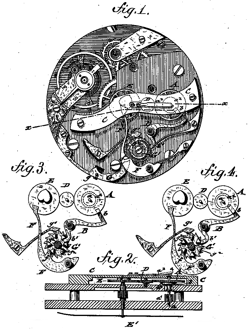
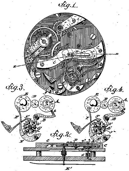
In the accompanying drawings, Figure 1 represents a top view of our improved stop-watch, in which the operating parts are shown in a position of rest, with the quarter-second hand at zero. Fig. 2 is a detail vertical transverse section of the same on line x-x, Fig. 1; and Figs.3 and 4 are detail top views, showing the operating parts of the stop-watch, respectively, in position for starting and stopping the quarter-second hand.
Similar letters of reference indicate correspending parts.
The timing attachment of our improved stop-watch is set in motion by the third wheel of the watch-movement by means of an intermediate arbor carrying a pinion which meshes with the third wheel and a gear-wheel for transmitting motion to the timing attachment. This has the advantage that all the parts of the timing attachment move more briskly than when actuated by the second-wheel, and do not exert any retarding infinence upon the motion of the movement itself, so tat that the quarter-second hand may be permitted to move with the watchmovement for thirty-six hours (more or leas) in a regular and reliable manner without in the least affecting the regular motion of the latter.
For the purposes of our invention a gear-wheel A, having regular teeth, is placed on the intermediate arbor a, which latter carries at its lower part a pinion a', that meshes with the third wheel of the watch-movernent, and is thereby continuously kept in motion. The gear-wheel A is provided at its under side with a beveled conical disk a², that is readily engaged by the edge of a nose b of a falcrumed and spring-pressed lever B. The arbor a of the gear-wheel A is extended upward through a hole of a bridge C, that is secured to the top plate of the movement and acted upon by the free end of a spring a³, attached to the bridge C. The bridge C, together with the top plate of the movement, supports also the arbors of an intermediate slightly-conical pinion D, and of the usual heart-wheel E, and quarter-second hand E'. The intermediate slightly-conical pinion D, meshes wich thet heart-wheel A at one side and with the heart-wheel at the opposite side, said heart-wheel having teeth with square edges, like the gear-wheel A. The heart-wheel E is operated by a fulcrumed and springpressed shifting lever F, which acts upon the heart-cam of the gear-wheel E in the usual well-known manner in chronographs of this class. By the action of the spring a³ on the arbor a the gear-wheel A is thrown into mesh with the intermediate pinion D, as soon as the beveled nose b of the lever B is withdrawn. When the nose of the same engages the conical disk a² of the wheel A the same is instantly raised out of contact with the intermediate pinion D, and thas the quarter-second hand brought to a stop.
The mechanism by which the shifting and stopping levers F and B are actuated is the same which is usually employed in stop-watches, and consists of an actuating-lever G, having a flnger-stud g, projecting through the case of the watch, and of a double ratchet-wheel G', having a cheek-pawl g'. The ratchet-wheel G' carries an its upper surface triangular studs g', which, together with intermediate recesses between the studs, actuate the stopping and shifting levers B and F. The shifting-lever F is for this purpose provided with a projecting heel f, and the stopping-lever with a heel b'. The different positions of the shifting and stopping levers when the quarter-second hand is at the starting-point or in motion or in a position of rest are respectively shown in Figs. 1, 4, and 3.
The Operation of the timing attachment is as follows:
For starting the quarter-second hand the lever G is depressed and the ratchet-wheel G' moved forward for the distance of two teeth, which causes the heel b' of the lever B to drop in between two studs g², while the heel f of the shifting-lever F is made to ride one of the studs g², as shown in Fig. 3. The levers B and F are thereby moved away from the conical disk a² of the gear-wheel A and the heart-cam of gear-wheel E, respectively. The downward pressure of the spring a³ on he arbor a causes the intermeshing of the gear-wheel A with the slightly-beveled transmitting-pinion D, and thas the instant starting of the quarter-second hand. For stopping the hand the lever F is depressed a second time, whereby the ratchet-wheel is again moved forward for two teeth. The shifting-lever F moves along the stud g² and is kept away from the heart-cam, while the heel b' of the starting-lever B is also engaged by one of the studs, so that the lever B is thrown toward the disk a² of the gear-wheel A, raising the latter and taking it out of mesh with the intermediate pinion D, as shown in Fig. 4. As the square edges of the gear-wheels A and E mesh only at their lower corners with the slightly-conical intermediate pinion D, the intermeshing or withdrawing of the gear-wheel A takes place almost instantaneously, so that consequently the starting and stopping of the quarter-second hand takes plane without any advancing or recoiling motion. For returning the quarter-second hand to the starting-point, the lever F is depressed a third time, whereby the heel of the shifting-lever F is dropped into one of the recesses between the studs, so that its enlarged end engages the heart-cam and shifts the quarter-second hand back to the starting-point. The heel of the stopping-lever B is engaged by the next adjoining stud g², so as to retain the gear-wheel A in raised position without allowing it to mesh with the intermediate pinion D, as shown in Fig. 1. In this manner the different operations of starting, stopping, and returning the quarter-second hand are accomplished in a reliable manner by a simple, durable, and reliable mechanism, which is not liable to get out of order, and which supplies a chronograph of great accuracy of operation and regularity of motion.
Having this described our invention, we claim as new and desire to secure by Letters Patent:
As an improvement in stop-watches, the combination of a vertically-movable gear-wheel receiving continuous motion from the third wheel of the watch-train, said gear-wheel having a beveled disk at the under side, a stopping-lever engaging said disk, a spring pressing on the arbor of said gear-wheel, a beveled transmitting-pinion, a quarter-second wheel, carrying a heart-cam, and a shifting-lever, substantially as described.
In testimony that we claim the foregoing as our invention we have signed our names in presence of two subscribing witnesses.
Auguste Henchoz-Arnold
Fritz Henchoz-Huguenin
Dateiversionen
Klicke auf einen Zeitpunkt, um diese Version zu laden.
| Version vom | Vorschaubild | Maße | Benutzer | Kommentar | |
|---|---|---|---|---|---|
| aktuell | 13:58, 11. Aug. 2012 | | 820 × 1.088 (628 KB) | Holger (Diskussion | Beiträge) | {{Kategorie Bildgalerie Archiv Henchoz Freres}} |
Du kannst diese Datei nicht überschreiben.
Dateiverwendung
Die folgende Seite verwendet diese Datei: