Datei:US Patent 733.219 Matthaeus Klingler Schramberger Uhrfedernfabrik GmbH..jpg
Originaldatei (584 × 827 Pixel, Dateigröße: 91 KB, MIME-Typ: image/jpeg)
US Patent 733.219 Matthaeus Klingler Schramberger Uhrfedernfabrik GmbH.

|
Alle Bildrechte liegen bei United States Patent Office. Diese Abbildung ist urheberrechtlich geschützt und steht nicht unter einer freien Lizenz. Für anderweitige Nutzungen außerhalb von Watch-Wiki ist die schriftliche Zustimmung des Urheberrechtsinhabers nötig. |
Description
PATENTED JULY 7, 1903.
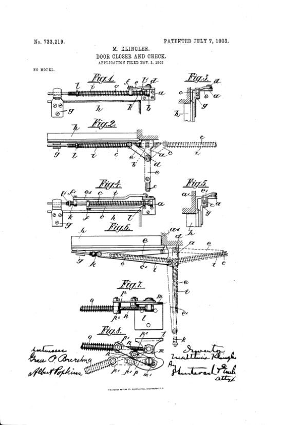
M. KLINGLER. DOOR CLOSER AND CHECK. APPLICATION FILED NOV. 3, 1902 N0 MODEL. UNITED STATES MATTHAUS KLINGLER, OF OBERNDORF, GERMANY, ASSIGNOR TO THE SCHRAMBERGER UHRFEDERN FABRIK GESELLSCHAFT MIT BESCHRAENKTER HAFTUNG, OF SCHRAMBERG-WURTEMBERG, GER MANY.
DOOR CLOSER AND CHECK. SPECIFICATION forming part of Letters Patent No. 733,219, dated July 7, 1903.
Application filed November 3,1902. Serial No. 129,884. (No model- To all whom it may concern:
Be it known that I, MATTHAUS KLINGLER, a citizen of the German Empire, residing at Oberndorf, in the Kingdom of Wurtemberg, Germany, have invented certain new and useful Improvements in Door Closers and Checks, of which the following is a description, reference being had to the accompanying drawings, and to the letters of reference marked thereon. The present application relates to a simple apparatus for closing doors and for keeping them in certain fixed positions, in which a movable arm, to which is attachable a movable collar, is fixed to the frame of the door and which on the opening of the door presses together a loose spiral spring wound around a rod, by which a second spiral spring, situated on the same rod before or behind the collar, can extend itself. By this means on the shutting of the door the full force of the first spiral spring is not exerted only on the door, but the force of the recoil of the spring is to a certain extent compensated for. The accompanying drawings show an apparatus embodying my invention in different forms of constructions.
Figure l is a front plan View. Fig. 2 is a Fig. is a bottom plan view of one form of construction, while Fig. 4 is a front plan view. Fig. 5 is a bottom plan view, and Fig. 6 a top plan view of another form of construction. Same characters designate same parts in all views. A third simplified form of construction is illustrated in Figs. 7 and S, in which the action of one of the two springs in the first form of construction is obtained by means of the movable disposition of an arm, with its collar exercising a pressing action. A plate a, bent at right angles, is affixed to the frame of the door 0. immediately next to that edge of the door on which the door itself turns. This plate a serves as a support to the rod 0, turning on the pivot Z). At the same time a movable arm 6 turning on the pivot d, and on whose free end is a collar f, adapted to slide on the rod 0. The free end of the rod lies loose in a fork-shaped guide g, attached to the door 7L. Now when the door is opened the rod 0 turns on the pivot Z), and the collarf, on account of its disposition on the movable arm 6, slides on the rod 0. \Vith a view to an autom atical quiet closing of the door two spiral springs z' and 7c are wound around the rod 0, of which the one, i, is somewhat longer and stronger than the other, 7o. Both springs bear against the collar f. The stop or abutment for the free end of the spiral springs is obtained by means of the nuts Z and Z, which can be so screwed onto the red as to regulate at will the tension of the two spiral springs t and it, either to increase it. To diminish it, on opening the door h the spring 'iis pressed together, so that the door is automatically closed by the extension of the spring. The violent banging to of the door is avoided by the disposition of the second spring 7c, which extends itself by the forward movement of the collar f, because by means of this spring the recoil of the collar is parried and the spring 1' can only push the collar f slowly back and to press the spring 7; together.
The second form of construction only diifers from the above description in that the collar f is only attached to the stronger spiral spring i, while a second arm 6, with its collar f also turning on the plate a, furnishes the stop or abutment for the weaker spring 7a, which can be pressed together by means of the collar f. In this case the spring 7c is situated in front of the spring'i. In this form of construction each spring is acted upon by a separate arm, and the weaker springis pressed together just as the stronger spring. After the collar f, however, has passed its highest point then .the spring is free and assists the stronger spring in its closing action. The closing of the door is therefore brought about in a similar way to that obtained by means of the wellknown pneumatic closer, inasmuch as the door in its course immediately it reaches a certain point is checked, and after the checking action is over the small spring 7o assists the stronger spring 1' to finally close the door. The door on being half or completely opened is automatically kept in either of these positions by means of the disposition of the arms. In every intermediate position, however, the springs exert their respective action-that is, they close the door.
The third form of construction diifers from the first in that the action of the shorter is obtained by means of the movable disposition of an arm with a pressing action. In this form of construction the movable arm n, with the spring 0, which correspond in their action to the parts a and 'i in Fig. 1, is fastened to and turns on the plate m, which has two noseshaped rounded-off corners. The part of the plate Z which is bent ofi serves for fastening the plate to the door-frame. An arm p is fixed to a groove m of this plate m, disposed in such a manner that it can move in this groove, and on its other end having a collar which slides up and down the rod 01. In a groove of this arm is attached an adjustable roller piwhich rolls around the inner edge of the plate m. 011 moving the door forward or backward the roller 1) rolls along the edge of the plate m, and so around its projecting nose-shaped extremities, and thus causes the extension of or pressing together of the spring 0 by means of the lever 19 pushing forward or pulling back the collar 13 The working of the apparatus is exactly the same as in the first form of construction.
Having now fully described my invention, I declare that what I claim is- 1. A door-closer comprising a bracket for attachment to the door-frame, a rod hinged to the bracket, a guide for attachment to the door, and through which the outer end of the rod freely slides, a spiral spring encircling the rod, an abutment for the outer end of the spring, a sliding collar on the rod, at the inner end of the spring, and an arm pivoted at one end to the said bracket, and at its other end pivoted to said sliding collar, substantially as described.
2. A door-closer comprising, a bracket for attachment to the door-frame, a rod hinged to said bracket, a guide for attachment to the door, and through which the outer end of the rod freely slides, a spiral spring encircling the rod, an abutment for the outer end of the spring, a sliding collar at the inner end of the spring, a shorter spring at the inner side of the collar and an arm pivoted at one end to the bracket and at the other end pivoted to said collar; substantially as described.
3. A door closer and holder, comprising a bracket for attachment to the door-frame, a rod pivoted at one end to the bracket, a guide for attachment to a door and through which the outer end of the rod freely slides, a spiral spring on the rod, a sliding collar on the rod, at the inner end of said spring, an arm pivoted at one end to the bracket directly in front of, and in line with the rod-pivot and extending thence at an angle to the sliding collar to which it is pivoted, whereby the action of the spring through the medium of the said arm will hold the door fully open, fully closed, and also when swung at right angles to the frame, to bring the rod-pivot and arm-pivots in line; substantially as described.
4. A door-closer comprising, a bracket for attachment to the door-frame, a rod hinged to the bracket, a guide for attachment to the door, and through which the outer end of the rod freely slides, and a spring-pressed link mechanism pivotally connected to the bracket and slidingly connected to the rod; substantially as described.
In testimony whereof I affix my signature in presence of two witnesses.
MATTHAUS KLINGLER.
Witnesses:
A. S. DRAUTZ, ERNST ENTENMANN.
Dateiversionen
Klicke auf einen Zeitpunkt, um diese Version zu laden.
| Version vom | Vorschaubild | Maße | Benutzer | Kommentar | |
|---|---|---|---|---|---|
| aktuell | 13:42, 4. Mär. 2021 | | 584 × 827 (91 KB) | Andriessen (Diskussion | Beiträge) | US Patent 733.219 Matthaeus Klingler Schramberger Uhrfedernfabrik GmbH. {{Bildrechte U|United States Patent Office}} {{Kategorie Bildgalerie Archiv Schramberger Uhrfedernfabrik}} |
Du kannst diese Datei nicht überschreiben.
Dateiverwendung
Keine Seiten verwenden diese Datei.
- Bildgalerie Archiv Schramberger Uhrfedernfabrik
- Picture gallery archive Schramberger Uhrfedernfabrik
- Galería de imagenes archivo Schramberger Uhrfedernfabrik
- Afbeeldingen galerij archief Schramberger Uhrfedernfabrik
- Фотогалерея Архив Schramberger Uhrfedernfabrik
- Galleria fotografica di Archivio Schramberger Uhrfedernfabrik